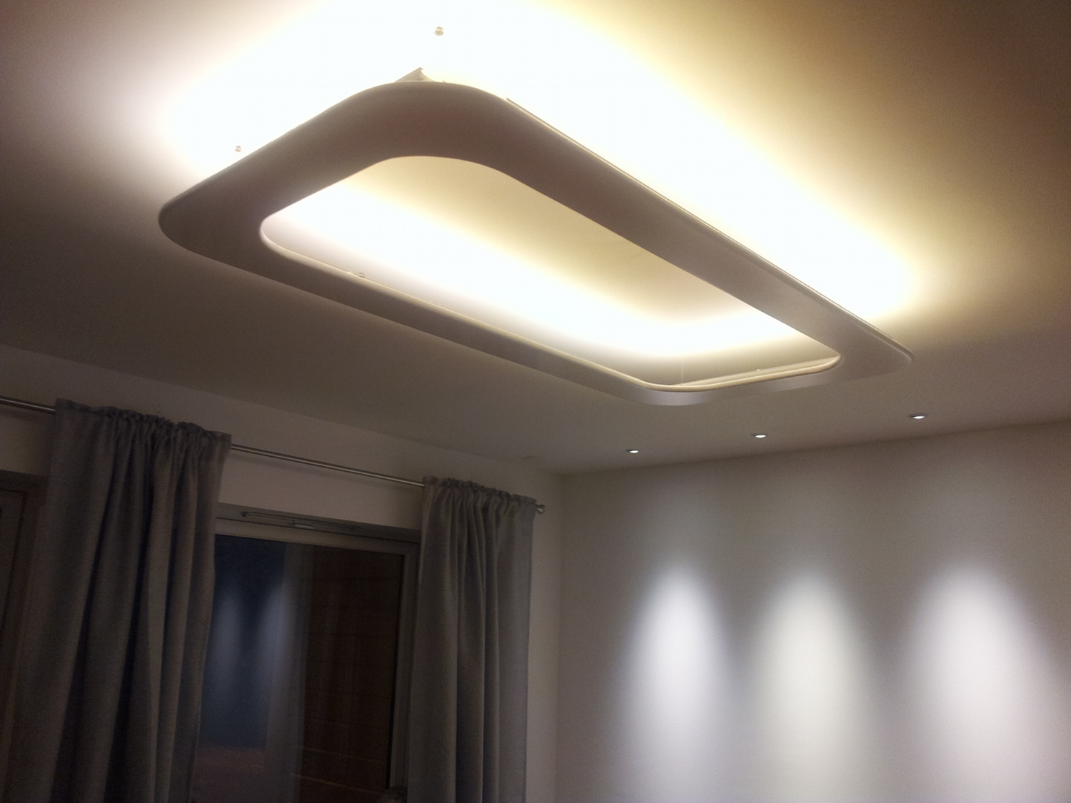
I was meaning to put this up for quite a while now. Back in 2011, I designed and built a ceiling lamp which I wanted to share.
Goal
It started out when we wanted to improve the lighting situation in our living room and I was initially looking for an off-the-shelf lamp which full fills our needs:
- potential to provide a lot of light (>8000 lumens for our ~30m^2 room)
- dimmable
- indirect lightning
- minimalistic (& invisible?) design
- low power (LED)
- controllable from a computer/smartphone
One would think that in 2011 this kind of lamp would be main stream, but it turned out to be quite hard to find a lamp (or two) which would fit our needs. This is why I started to play with the idea to design and build my own.
Design
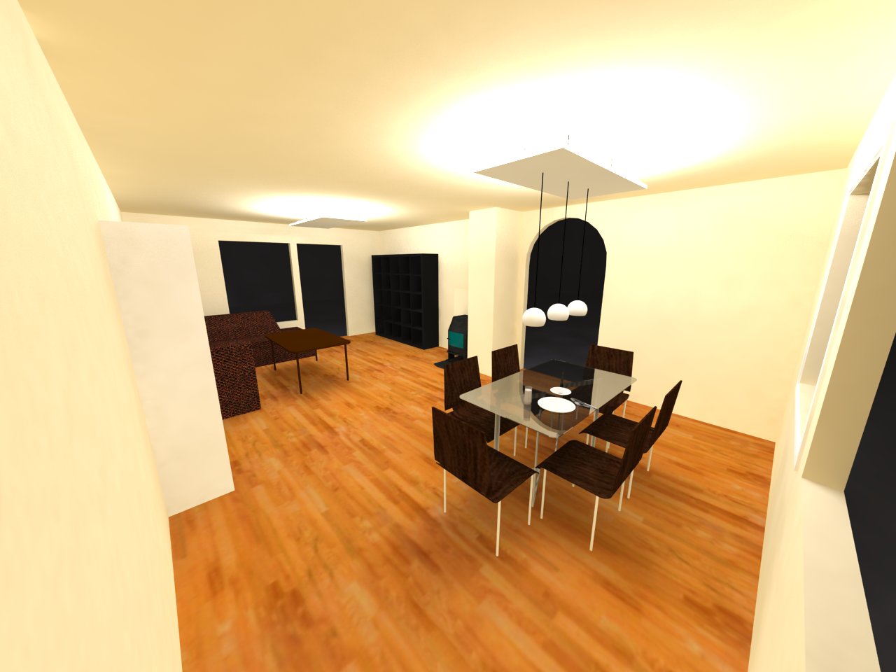
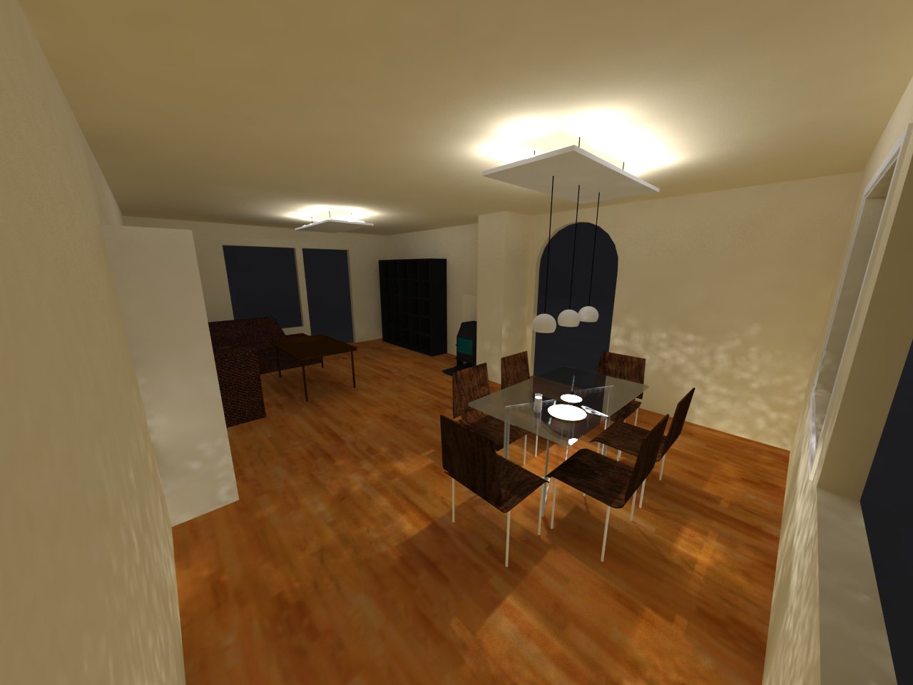
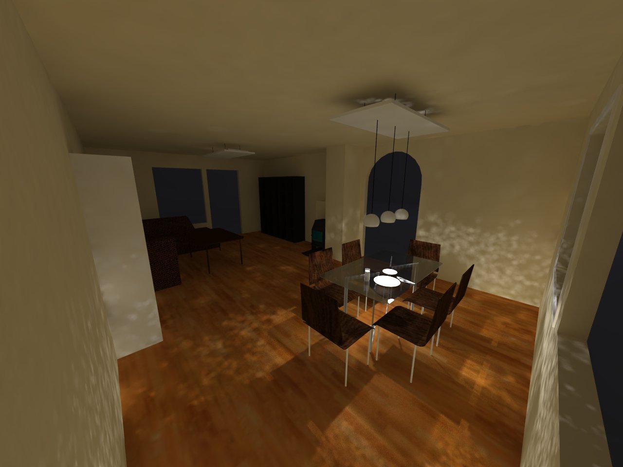
One thing was clear right from the beginning: the lamp was going to be based on LED’s. I’ll spare you the many failed designs I have tried before I ended up with a good compromise. The following images are rendered with V-Ray plugin for Google Sketch up, which I was using to play around with different solutions. This tool gave me the possibility to try out lamp designs and render how the light would approximately distribute in the room. The images below show two ceiling lamps installed in the room which are A) at full power, B) 50% dimmed and C) only the pendant lights over the table on.
For this project I’m using Cree XLamp XP-E High Efficiency White LED @ 2700K, which produces warm white light. As I was playing with some of those little LED’s, I quickly learned that I had to put serious thought into cooling. Although the total heat dissipation compared to for example a halogen lamp is small, the core at the LED gets hot rather quickly if not cooled properly which will shorten it’s life time. I tried several solutions with different heat sinks and thermal paste, but the only real solution which would last was to solder the LED on a metal-core PCB which in turn is mounted on a heat sink. This special type of PCB is not made from traditional FR-4 material, but is basically a piece of aluminium with a thin isolation layer between the PCB tracks and pads and the metal core. The aluminium conducts the heat away from LED much quicker than a FR-4 based PCB can, because FR-4 has quite a high thermal resistance. Check out this wikipedia page for more info.
Now knowing that all LED’s need to be mounted on heat sinks and knowing that I needed a lot of metal to cool all those LED’s which adds quite some wait to the lamp, I had to re-think my design and came up with the following final design:
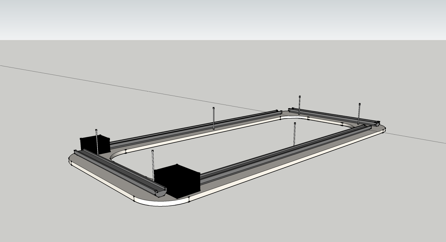
Four aluminium profiles mounted on top of a wooden frame which is painted white with a high gloss finish. The two black boxes are place holder for the electronics needed to drive the lamp. The idea is that when this lamp is mounted on the ceiling, one would not see the aluminium profiles, the electronics and the LED’s when looking at the lamp.
LED configuration
The LED’s I have chosen for this project are rated at maximum of for 1A. At this current, the LED will output 228 lumens. However, this is not the most energy efficient configuration. At lower current, the LED is more efficient although it outputs less lumens. Therefore it makes more sense to drive the LED’s with lower current but use more LED’s to compensate for the brightness.
So I decided to go for a configuration with 350mA per LED with double amount of LEDs. This gives me actually more lumens in total because half the current doesn’t mean half the lumens. The amount of lumens the LEDs produce at half the current is more then half the lumens at 700mA. So driving them with 350mA increases efficiency and makes them easier to cool. Downside is of course costs since I have to buy double the amount of LEDs.
Driving with lower current increases also lifetime. The manufacturer predicts 35.000 hours lifetime when running at 700mA. That means 12 years when using the lamp for 8 hours every day. But given the lamp will probably be used about 2 hour per day on average and the current will be half, I expect the LEDs to basically last forever (assuming the soldering process doesn’t damage them though).
Power supply
To provide the 350mA for each LED a constant current driver is needed. I looked at several options and figured it would be easiest to chose a off-the-shelf solution. The LuxDrive 7021-D-E-700 are small drivers which can be controlled via PWM, which is what I need for dimming and on/off control.
Wireless control
The goal was to control the lamp from my Android smart phone. The way I can accomplish this is the same way I control my garage door: A REST webservice running on my server accepts input from my phon (or a webpage) which then sends out a 433Mhz RF signal (using my transceiver connected to my server) to a RF receiver installed on the lamp. The receiver board would then generate a PWM signal to set the requested dim value on the lamp. Using 8-bit where 0 means off and 255 100% on, gives plenty of possible dim positions.
Schematic
Here is a very high-level schematic of how I put everything together for one lamp. Note: I’m building two lamps to achieve the 8000 lumens.
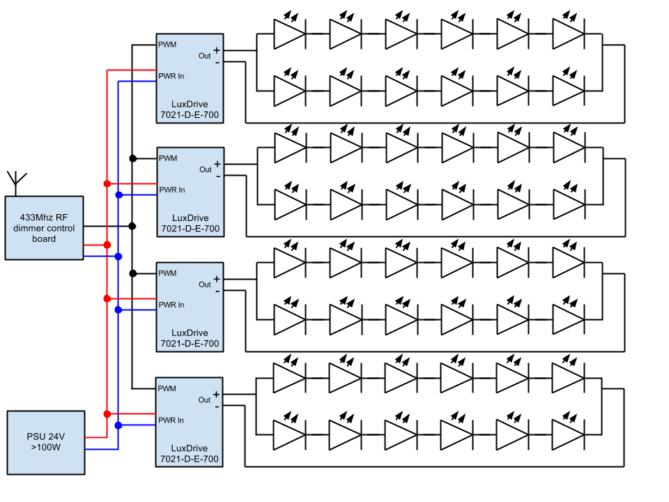
The voltage drop of one LED running at 350mA is 3V. This gives a drop of 18V for one series of 6 LEDs. The LuxDrive units produce 700mA which is split over two series which get 350mA each. A 24V power supply provides the required 24V DC input for the LuxDrive units to drive the LED’s at around 18V. The control board with the RF receiver has a voltage regulator which steps the voltage down to 5V, which is what the PIC16F690 microcontroller I’m using for this projects needs. When the board receives a RF command, it will generate the PWM signal for the LuxDrive unit which then switches the LEDs on and off at high frequency (I’m using 600hz) to achieve the set dim value.
In case one LED would fail, one series of six LEDs will stop functioning and the sibling row will get double the current (e.g. 700mA). But because the LED’s are designed to run at 700mA, this is not going to be any problem at all. One will only notice a brightness change in the lamp.
Control board
For the control board I’m using components which I’ve written about on my blogg before: PIC16F690 micro and AM-RRQ3-433 rf receiver. One micro is used to decode the incoming RF signals while a second micro is used to generate the PWM signal to the LuxDrive units.
Here are some pictures showing the schematic, PCB layout and assembled board:
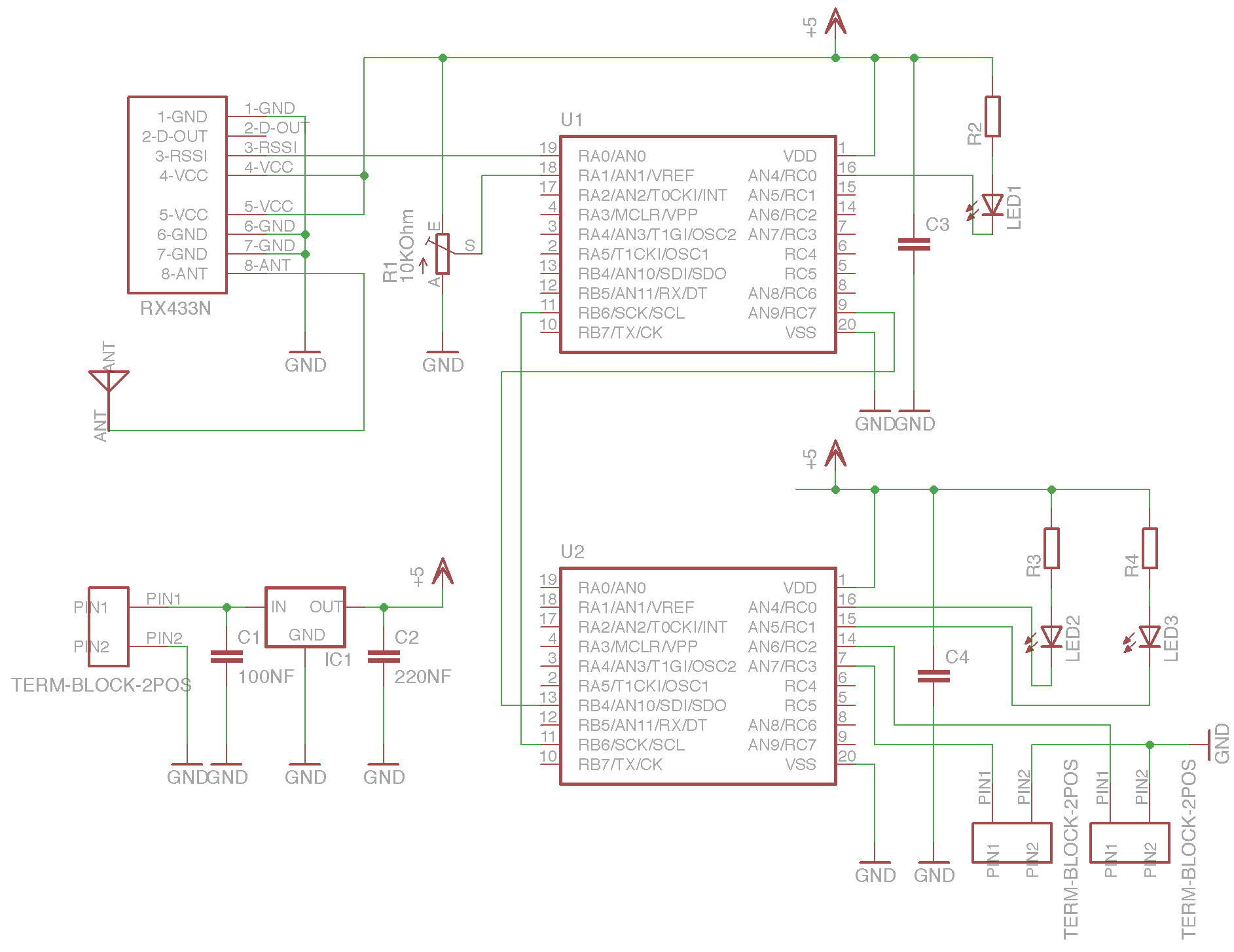
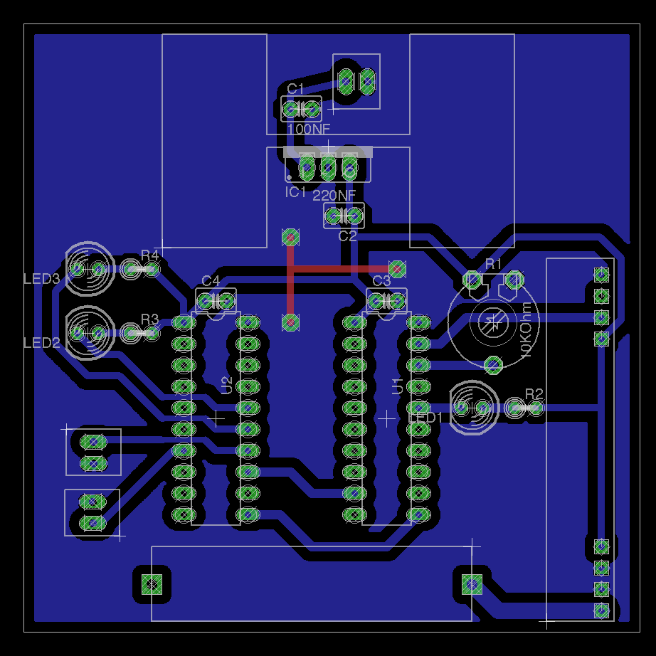
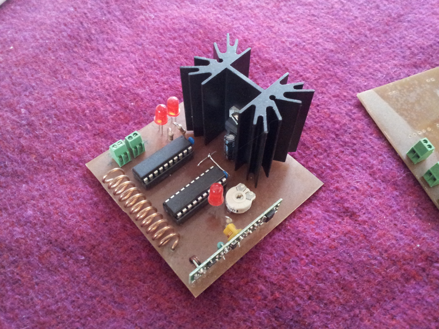
This board I’ve just etched myself as you can see.
I also etched another PCB which just has the LuxDrives on it to distribute the power to the LED’s:
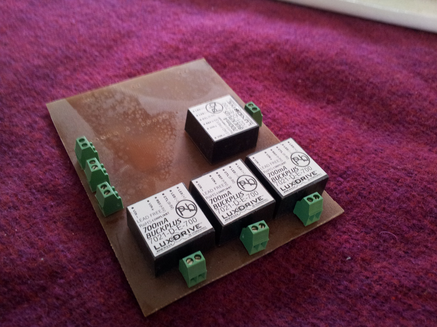
Building
Building the wooden frame for the lamp was fun. I basically bought a particle board and cut out the shape of the frame and sanded and painted over and over again until I got the high gloss finish I wanted. Google and youtube are great sources for learning how to do that.
Next step was to solder all the 96 LEDs (+ spare ones) onto the metal-core PCB stars which I bought for this project. I didn’t quite know how to solder those small 3×3 mm LED’s until I figured I could just use my ceramic top in the kitchen. I used my IR-termometer to set the required 215 degrees Celsius (+ some more) and then simply placed each PCB with a LED positioned on it on the ceramic top until the solder melted and the LED “fell” into place. Before I did this, I made sure I had some solder on the LED and on the PCB. This has worked out OK for me (I had to replace a few LEDs once they were installed on the lamp) but next time I’m going to solder SMD LEDs, I will use a hot air gun.
Once all LEDs were soldered and tested, I mounted 48 of them one the aluminium profiles and connected them in series as shown in above schematic.
Installation
The lamp weights about 11kg with those heavy aluminium profiles. The weight is distributed over four mounting points in the ceiling using heavy duty 15kg fishing line. The fishing line is almost invisible such that it looks like the lamp is hovering under the ceiling.
Final product
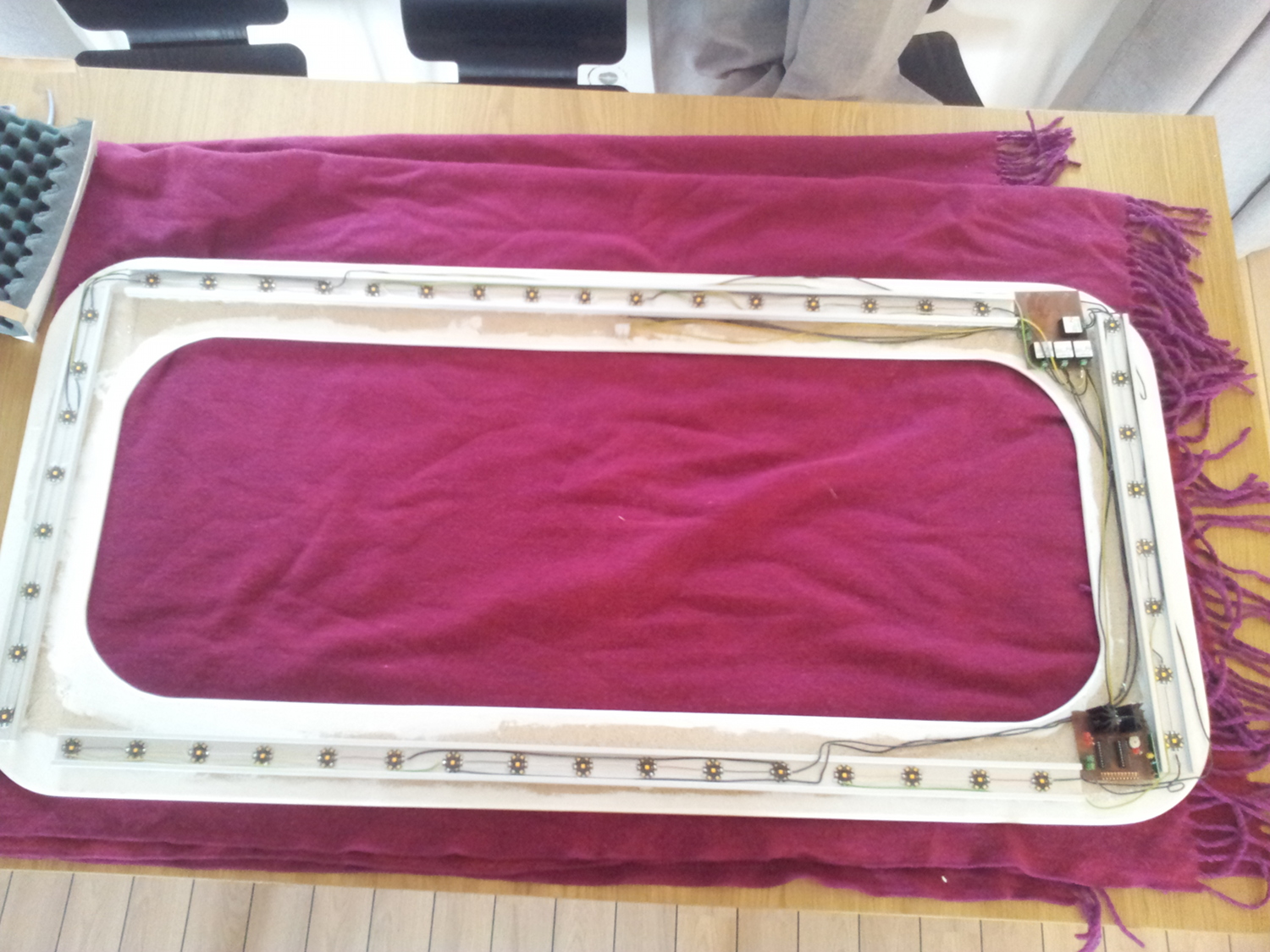
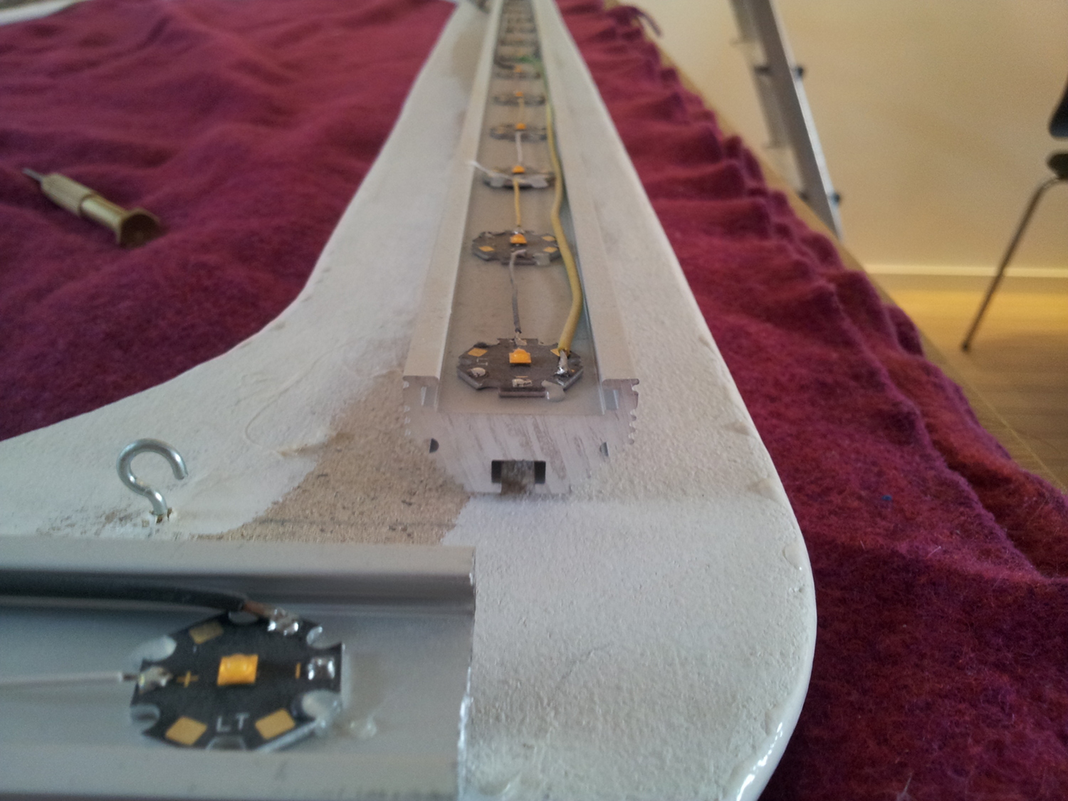
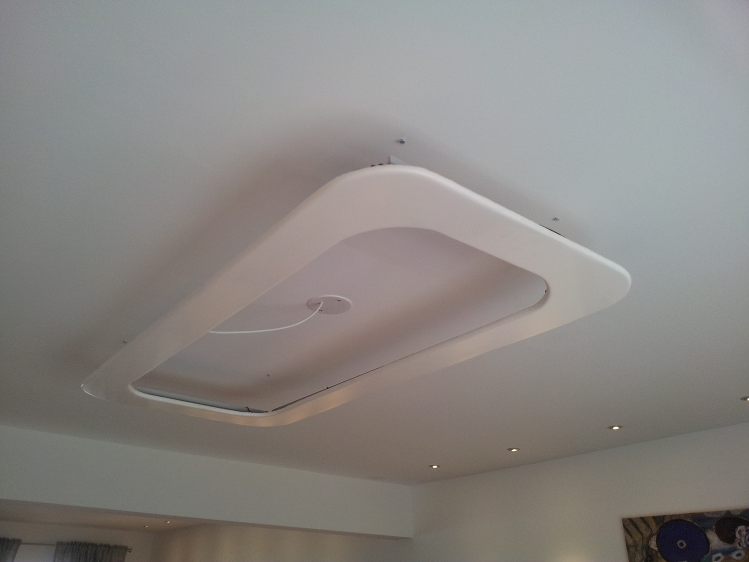
Usage
We feel that setting the two lamps to 25% dimmed gives enough light for daily use. Given one lamp consumes about 60Watt when running at 100%, we are using about 30W of enery for the entire room. Not bad.
Demo
Bill of materials
- 8 Aluminium profiles from led-tech.de
- 100 metal-core PCB star for X-Lamp from led-tech.de
- 100 Cree XLamp XP-E High Efficiency White LED @ 2700K from digi-key
- 8 Lux Drive 7021-D-E-700
- 2 Mean Well S-150-24 power supply
- 4 Microchip PIC16F690
- 2 AM-RRQ3-433 rf receivers from rf-solutions