The finished PCB has arrived quite a while ago now and has been assembled as well. Time to upload the final part of this project to see some results.
I selected Beta Layout as the PCB manufacturer for this project with quite satisfying results. I especially liked that they sent me automated pictures of the board after each manufacture step, which turned out to be very useful. Using those, I was able to detect that the holes had been drilled using the wrong drill sizes. They recognized this error and produced a new board with the correct hole sizes within the agreed delivery date.
The final board:
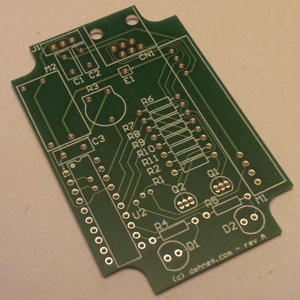
The solder mask, silkscreen and the plated holes are features that make the board look so much better, compared to a home made board.
Assembling the board was easy, especially soldering with plated holes is fun. Except the miscalculated package for the trim-pot (I had to use the square blue pot instead of a round shaped one), everything worked out well. Here is the assembled board:
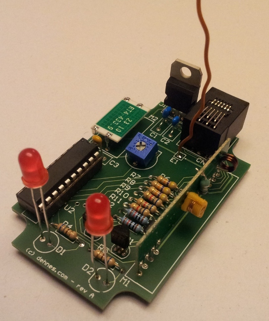
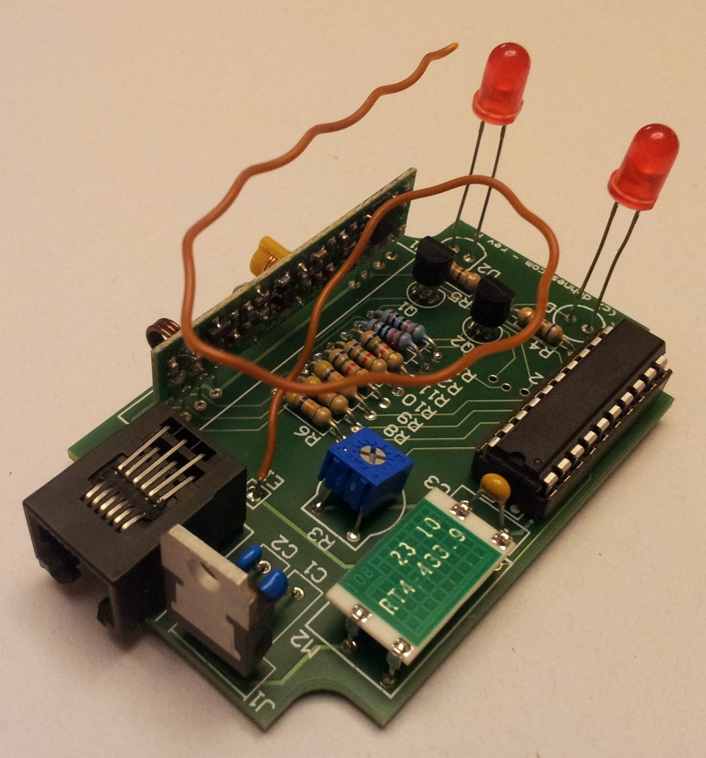
The orange wire is the antenna I’m using. It is good enough to bridge the distance to the garage. One of the LED’s blink when a RF signal has been received and the other LED blinks when a RF signal has been sent (such as the current status of the door and light).
This board fits nicely in the following case:
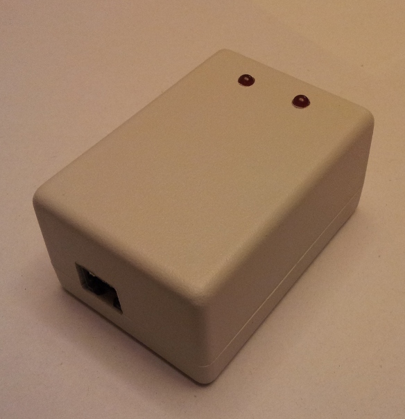
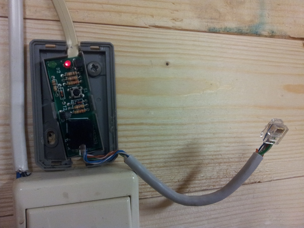
The final controller is then connected via the 6p6c jack connector to the existing door opener like this:
To open and close the garage door, I’ve written a simple Android app which talks to my home server via JSON/REST via wifi. This server has my general purpose RF transceiver connected to it which is used to communicate with this controller over 433Mhz RF.
Here is a short demo of the final application: