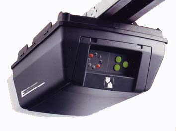
In my garage I have a door opener from the norwegian firm Edlandsporten. Here is a picture of the device and the official brochure:


Unfortunately, the included wireless remote controll has broken down and I need a replacement for it. I contacted the manufacture and they offered me a set of two new hand transmitters for a ridiculous price of 1000 NOK (~ 125 EUR). In my opinion, this is mad ness for such a cheap piece for hardware. After a short investigation on the Internet, trying to find cheaper alternatives, I decided to build my own and publish the project. This blog entry is the first part of the design and build process of this door controller.
Requirements
Since I’m building my own controller for the opener, I might just as well add all features which would be nice to have:
- It must be wireless.
- I want to control the door from my mobile phone. I don’t like the idea of having so many remote controls around my house and I try to do everything using my phone.
- One separate button for “open” and one separate button for “close” instead of one button for both functions. This is nice if you want to enforce closing the door and not accidently open it again.
- It must be possible to read the current status of the door.
Concepts
There are two possibilities to interface with the opener.
A) There is a three wire screw connector terminal on the device with let’s you open and close the door by basically connecting two of the three wires. This interface lacks dedicated “open” and “close” commands. You connect the two wires once for “open” and connected them again for “stop” or “close”. However, thinking of portability, this kind of interface is probably also available on door openers from other manufacturers and in case I need to replace it by a different brand, there is a good chance I can continue to use my external controller when using this interface.
B) There is also a switch mounted on the wall in my garage which is directly connected to the door opener by cable. This switch (single push button) allows you to open/close the door if you are not using the wireless hand transmitter. You can view it in the brochure above: the left most gray module of the four accessories. Inside this small wall switch, there turns out to be a small PCB which has a 6p6c jack connector on it, probably meant to connect multiple of those modules in series. I worked out what each of the pins function is and this is what I found out:
| Pin | Function |
|---|---|
| 1 | Pin has +25V if the light is off and 0V if light is on |
| 2 | +25V constant power |
| 3 | Ground |
| 4 | Pin has +25V if the door is in the “closed” or “middle” state and 0V is the door is “open”. This pin can also be used to give the “open” command to the opener by connecting it to ground; which causes a current of about 4mA to flow to ground from this pin. |
| 5 | Ground |
| 6 | Pin has +25V if the door is in the “open” or “middle” state and 0V is the door is “closed”. This pin can also be used to give the “close” command to the opener by connecting it to ground; which causes a current of about 4mA to flow to ground from this pin. |
Both Ground pins 3 & 5 have to be connected to make it work.
So I decided to use option B to interface with this Edlandsporten such that I can implement requirement 3 and 4.
To cover requirement 1, the controller will have a 433Mhz receiver such that I can send the “open” & “close” commands to it. It will also have a 433Mhz transmitter such that I can receive the current state of the door.
Requirement 2 will be implemented by building and Android app which talks to my home-server via the Internet (not part of this project). My home-server has my general purpose RF transmitter/receiver module connected to it such that the server can transmit the “open” & “close” command to the door controller and also receive the current state of the door from it.
Schematic
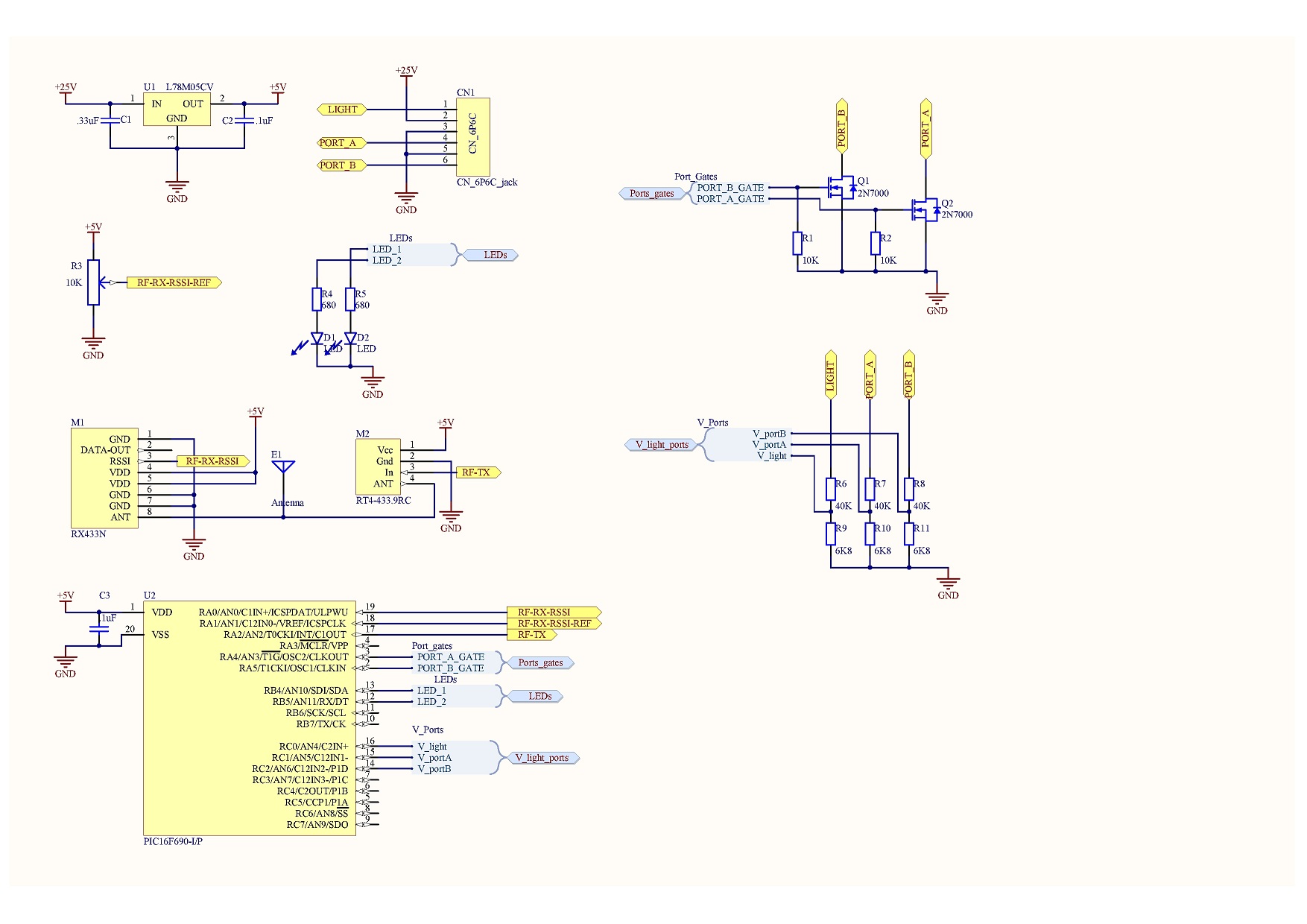
Here is the schematic I came up with:

I’m using a PIC 16F690 microcontroller as the brain of the door controller board. This chip has built-in oscillator and ADC (analoge-digital converter) such I can take measurements of pin 4 & 6 to detect in which state the door currently is. “Light” is pin 1 and let’s me detect whether the light is on and “PortA” and “PortB” represent pin 4 & 6 to do dedicated “open” or “close”. For receiving 433Mhz RF signals I’m using the RX433N. For transmitting I’m using the RT4-433.9RC RF module.
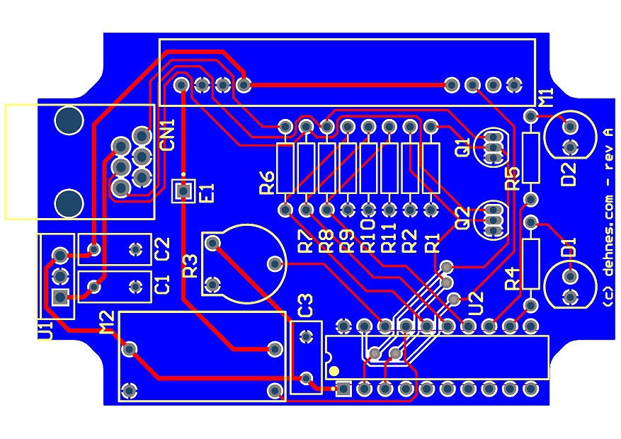
Although I have been making my own home-brew PCBs before, I decided I would try a professional PCB manufacturer this time to get a nicer board with solder mask and the silk screens. I’m planning to put the board in a plastic enclosure from the manufacture Hammond Manufacturing with part number 1594BSGY (digi-key part: HM222-ND). Here is the PCB design I have come up with so far:

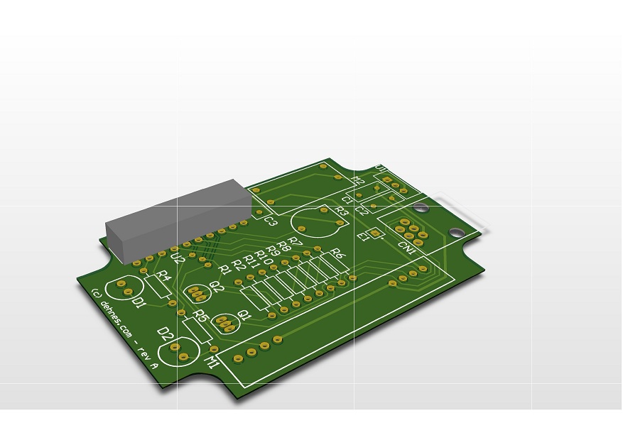
And here is the board in 3D view:

Now I’m sending the design files to a yet-to-be-chosen PCB manufacturer and get this board made.
In the next post, I’ll show you the final board, build it and open-source all project files, including the PIC firmware.