I designed and built my own EVSE EV Charging station from scratch because I wanted 2 stations with each 22kW support (3 phase, 400V, 32A) and "real-time" current & voltage measurements on all phases - in order to be able to do dynamic load sharing between the stations. E.g. if car-1 only uses 13A, the remaining 19A are allowed on the second station.
It was a real full stack project, reaching from hardware/electronics design all the way to the frontend webapp written in TypeScript.
Building your own charging stations is fun and gives you full control over the charging (assuming you like to code). It is also cheaper (see BOM below).
For example, you might only want to allow charging at those hours during the day when energy prices are low enough (our enery prices change on hourly basis) or when your solar system produces enough energy. Or you could want to throttle the charging speed dynamically to allow sharing of the line capacity with multiple charging stations when needed. Dynamically adjusting the charging speed to match the fluctuating output of your solar system is also possible.
Here is a little demonstration of the charging station and the app I wrote:
In the video, you will see:
- the charging station detecting the 32A-rated cable
- as the cable is plugged into the EV, it is detected by the charging station
- when charging is enabled in the app, charging starts
- when charging is disabled in the app, charging stops
Overview
The system architecture consist of the following 4 layers and their respective features:
-
Hardware
- ability to tell the car at which charging speed (0 means off) it can charge via the Pilot Control signal
- switch on/off the main contactor
- read back the car's charging state from the Pilot Control signal
- detect type of cable plugged in via Proximity Pilot signal
- measure actual current draw for all three phases
- measure voltage on all three phases
- uses a Arduino nano 33 IoT because it has the required 8 analog inputs and WiFi
- (there is no ground fault detection, use an external Type-B GFCI)
-
Firmware
- Arduino based - easy to program
- over-the-air (OTA) firmware updates - FTW. No need to open the enclosure each time
- use IP/TCP to connect to the server via WiFi and keep connection alive (re-connect if timeout)
- listen for events from the car and the server simultaneously
- upon state change from the EV, push notification to the server immediately
- all logging is buffered locally in RAM first, and then transferred to the server for long-term storage / debugging
- handle the following types of requests from the server:
- get all data
- install new firmware: over-the-air firmware upgrades
- switch on/off contactor
- set max allowed charge rate on Control Pilot at any give point in time. This can be adjusted fluently (even during ongoing charging), and the EV will follow as commanded. This is key to implement flexible load sharing in order to balance power between multiple charging stations.
-
Server software which controls everything
- accept new TCP connections from charging stations
- fetch all data parameters from the charging stations regularly and log everything to InfluxDB
- listen for push notifications from the charging stations and react upon them
- Load sharing: calculate maximum charging rate for each station sharing the same power line
- evaluate the charging logic state machine and send back updates (max charging rate + contactor on/off) to the charging station
-
A frontend webapp
- uses Websockets to listen for real-time updates
- show power consumption for all three phases
- 3 modes:
- On - allows charging whenever the EV is ready
- Off - does not allow charging at all
- Low-cost - allows charging only during hours with low energy prices
- influence load sharing preferences by setting a priority
The hardware
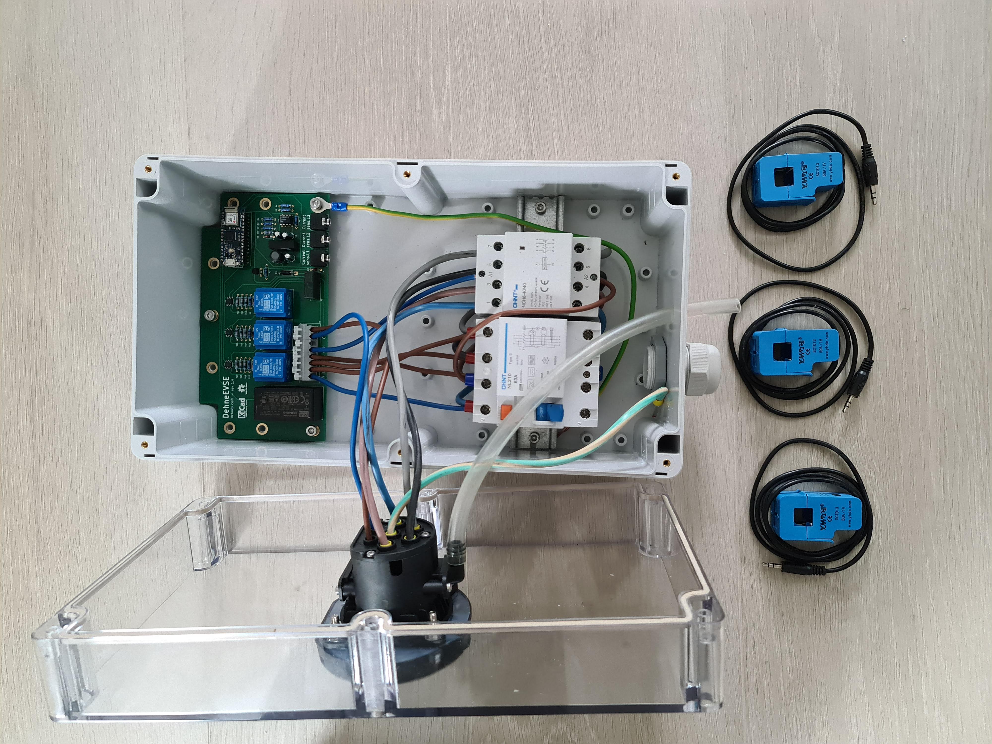
The main logic board handles all the communication (with the car and the server) and controls the main contactor accordingly.
The schematic and KiCad design files are all available on my Github account:
Here are some close-ups of the final PCB:
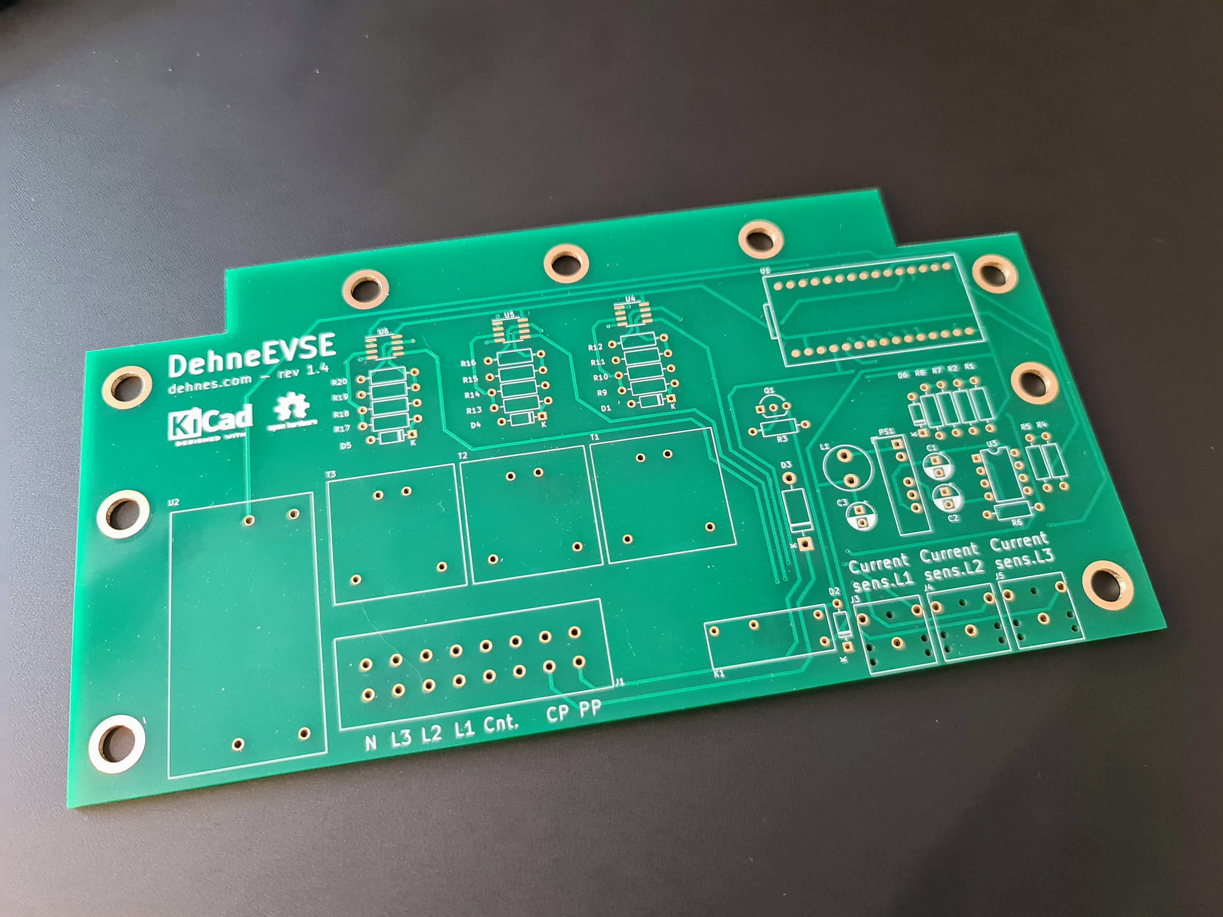
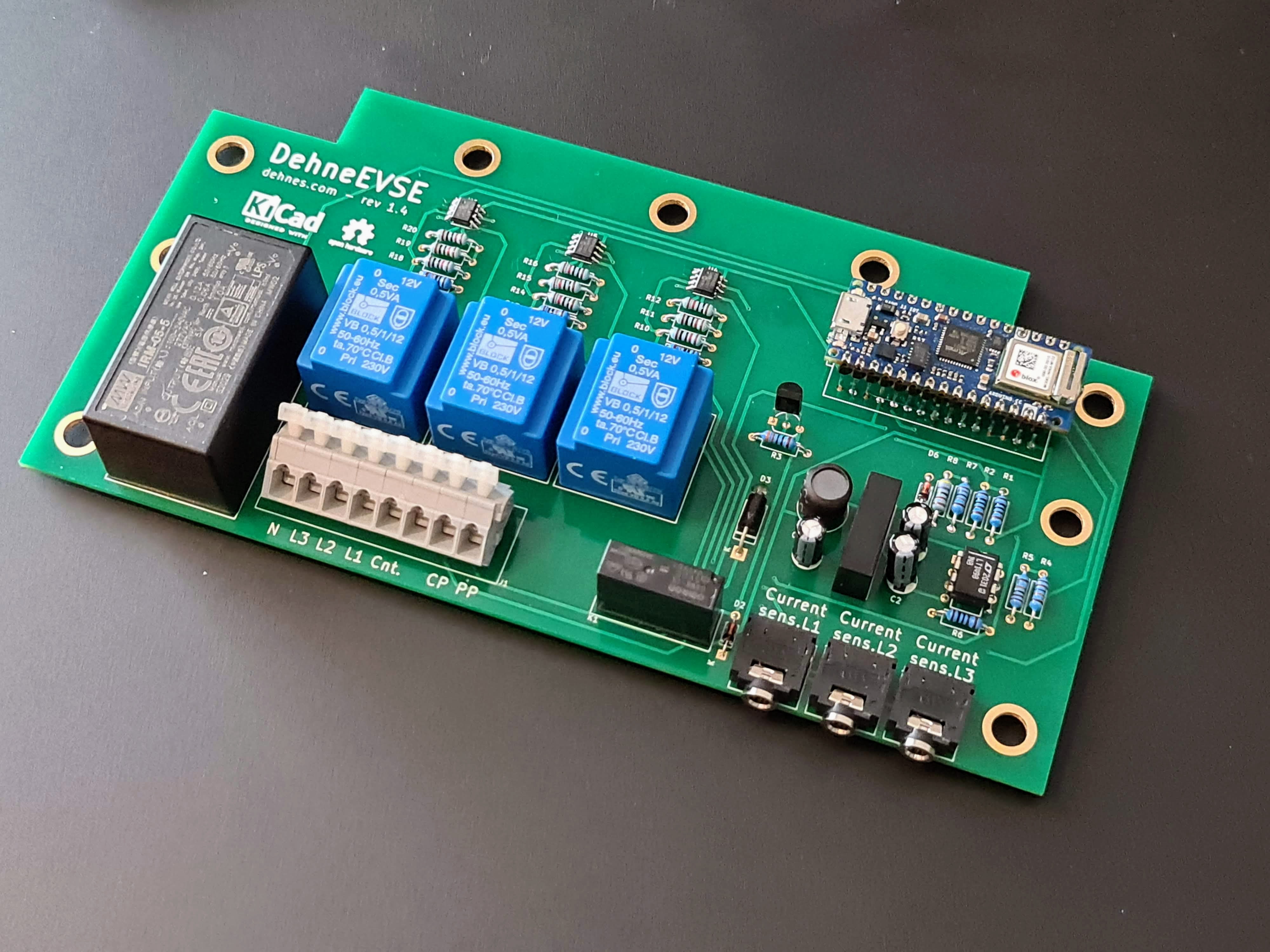
BOM PCB
Here is the Bill of Materials for the main logic board:
| Part | Reference | Cost in EUR |
|---|---|---|
| cap 1uf | C1, C2 | 0,09 |
| cap 2.2uf | C3 | 0,04 |
| diode 1N4148 | D1, D2, D4-D6 | 0,08 |
| diode TVS-P6KE16CA | D3 | 0,30 |
| Wago 256-408 | J1 | 3,00 |
| 3.5 mini jack - FC68131 | J3-J5 | 3,00 |
| G5NB-1A Relay 5VDC | K1 | 1,70 |
| Inductor 18uH - RLB0912-100KL | L1 | 0,30 |
| NMA0512SC DC/DC 5V -> -12,+12V | PS1 | 7,00 |
| R 1k | R1, R2, R6 | 0,15 |
| R 330 | R3 | 0,05 |
| R 120k | R4, R5 | 0,10 |
| R 180k | R7 | 0,05 |
| R 47k | R8 | 0,05 |
| R 100k | R9, R13, R17 | 0,15 |
| R 10k | 0,45 | |
| mini transformer VB_05-1-12 | T1-T3 | 13,84 |
| Arduino Nano 33 IoT | U1 | 21,00 |
| PSU IRM-05-5 | U2 | 10,80 |
| Op-Amp LT1498IN8 | U3 | 6,40 |
| Op-Amp MCP602T | U4-U6 | 1,5 |
| PCB manufacturing | 10,00 | |
| Total | 80,05 |
BOM Charging station
| Part | Cost in EUR |
|---|---|
| Main PCB (see above) | 80,05 |
| Enclosure IP65 RND 455-00205 | 42,00 |
| Contactor (Cenika NCH8-40 4NO) | 70,00 |
| Ground fault breaker Type B (Chint CV043889) | 130,00 |
| 3x SCT013-050 current clamp | 26,22 |
| Type 2 socket female 32A | 73,80 |
| cables and small materials | 20,00 |
| Total | 441,27 |
Here are some close-up of the final product:
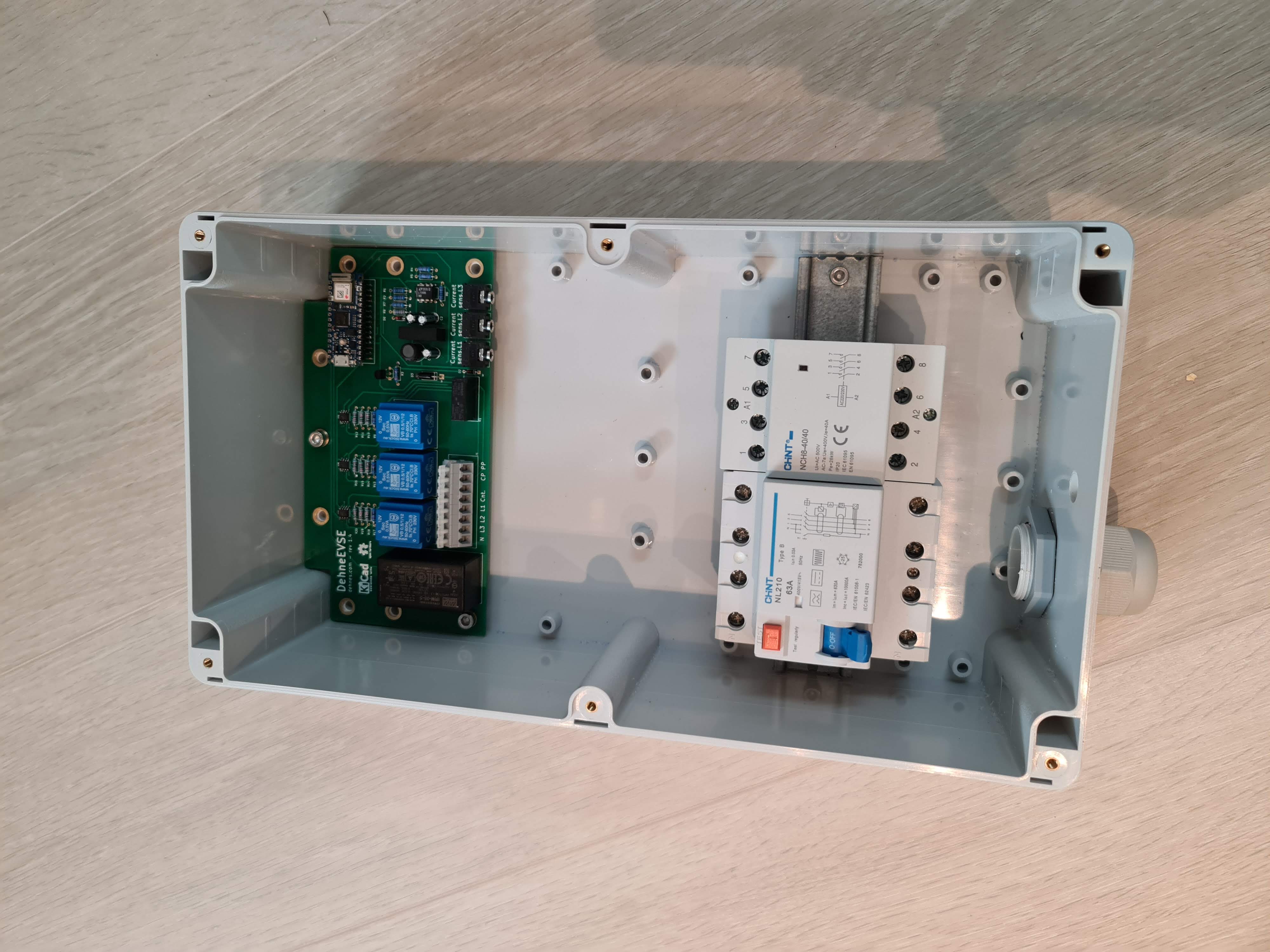
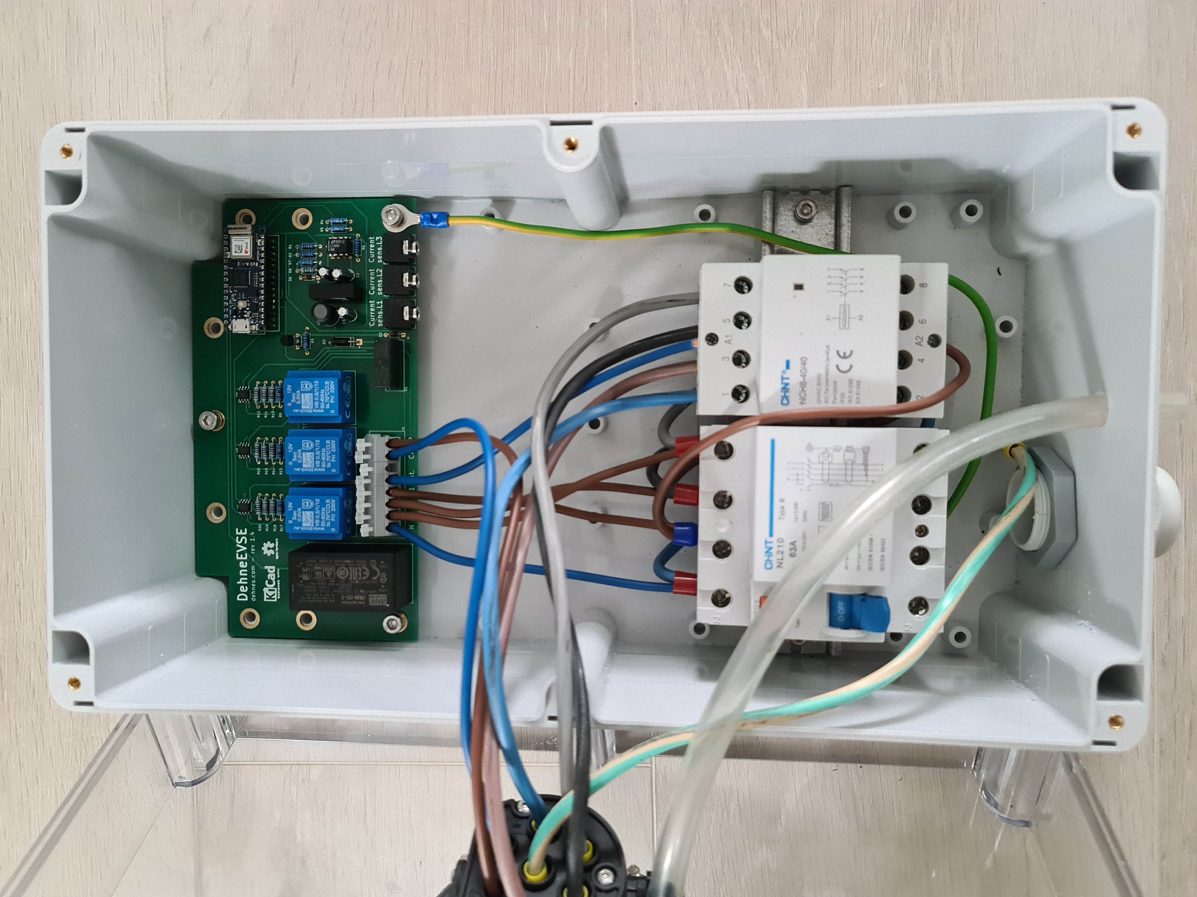
The firmware
The firmware for the Arduino Nano 33 IoT is written in C/C++ and I am using Platform IO as my IDE.
You can find the source code on my GitHub account as well.
I decided to let the server software (see below) handle all the charging logic, and thus the firmware only needs to forward commands to the car as instructed by the server software.
The main task of the firmware is to measure the voltage and current, as well as handle events from both the server (coming from the TCP connection) and the car simultaneously. Therefore, all I/O is coded non-blocking.
The software
Here is where all the main logic happens. The server software (written in Kotlin) accepts inbound TCP connections from charging stations, as well as inbound Websocket connections from the webapp. It regularly polls data from all connected charging stations and logs all data to InfluxDB.
It also executes the main charging logic and load sharing algorithm, to calculate at which rate each charging station is allowed to charge.
The source code is available on my GitHub account.
The webapp (see same github link above) is written in TypeScript and React and uses Websockets for full-duplex communication with the backend to display changes as they happen.
Graphing
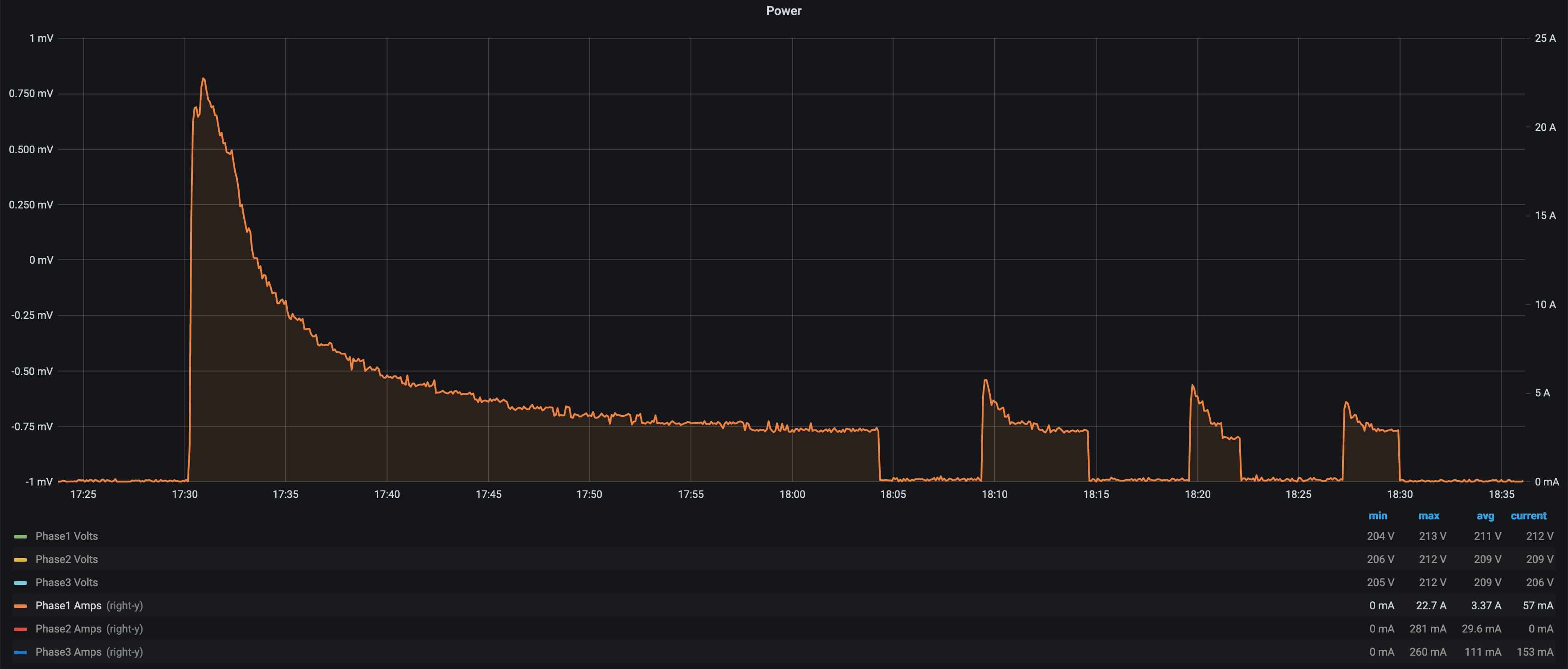
All data which is logged into InfluxDB can easily be graphed using Grafana.
Here is a graph of the current draw from a Nissan Leaf reaching 100% state of charge:
Future improvements
The only thing that is not working very well is measuring voltage. The problem lies in the small transformers being far from ideal for this purpose. The measured voltage is unstable and varies too much with temperature. There is not enough space in the enclosure for 3 large(r) transformers, so I am evaluating changing the design to using some special purpose IC instead of transformers.