In the scope of my personal home automation project, it is vital to know the temperature and humidity in rooms and outside. Besides logging this information and presenting it on a screen or on my cell phone or something, it can be used to control heating, air conditioning or ventilation. With this in mind, I built my own temperature and humidity sensor, which transmits it’s measurements to my central receiver (connected to my home-server) for further processing.
When designing and building this sensor, it was important to me to use cheap components, since I’ll be making at least 10 of them and spread them around the house. Another requirement was that the sensor should consume very little power, so that the battery would last for at least a year or so. A PIC micro-controller will be the brain of the sensor.
Wireless communication
First challenge to overcome was how to implement the wireless communication part. There are many different RF modules out there with different features. High end modules will handle the entire protocol including error correction and even encrypt the communication if you want, all you need is to write your message into the RAM memory of those modules and leave the rest to them. The XBee modules are such high end modules. Unfortunately, those modules are way too expensive for my project, so something cheaper was needed.
I decided to go for the 433Mhz band since this band has a large enough range to overcome in-door walls while still providing plenty of bandwidth for my relative small measurements. The transmitter module AM-RT4-433 and the receiver module AM-HRR3-433 from RF Solutions are most suitable for the job. They are relative inexpensive, but lack any kind of data encoding or error correction features. All this does is to either send HIGH or LOW (e.g. send nothing).
In order to be able to transmit any kind of data which is to be understood by the receiver, the bits needed to be encoded somehow (for example, how to transmit the value 11111111 when you only have HIGH and LOW? Send HIGH for x milliseconds?). Since there is only one communication channel (instead of two: one for data and one for the clock) and I didn’t want to worry about clock synchronization between the two end-points, I looked into using a so-called self-clocking signal. Manchester encoding is such an encoding algorithm; it provides both clock and content information at the same time.
But how to ensure reliability and error detection? At first, I wanted to use bi-directional communication in order to be able to send acknowledgements back to the sender, but this approach would also mean that the sender needs to be a receiver at the same time, which would have an unacceptable impact on power consumption (receiving data means you need to listen actively for incoming data). So the final strategy is to make the sensor a transmitter only, which simply sends it’s measurements at regular intervals. For error detected I decided to use CRC16.
The final protocol syntax which I was going to use looks like this. Each message (package) which is sent, consists of:
| Position | Contains | Length in number of bits |
|---|---|---|
| 1 | destination (e.g. receiver’s address) | 8 |
| 2 | source (e.g. sender’s address) | 8 |
| 3 | Message's length | 8 |
| 4...N | message’s body | (N-3) * 8 |
| N+1 | CRC16 value | 16 |
The receiver module is able understand the self-clocking signal and check’s the CRC16 for error detection before passing it onwards for further processing. The result is very usable, inexpensive and low power consuming wireless data transmission. The disadvantage with this approach is that it lacks any kind of security. Anyone can capture the signals and even send fake values to the receiver. Once those signals are going to be used to control something like heating or ventilation, a more secure communication channel is needed to prevent anyone in the neighborhood from doing anything nasty.
Measuring temperature
For temperature measurements I decided to simply use a thermistor together with the PIC’s internal 10 bits ADC (analog-to-digital converter). This solution is very cheap and by using a suitable thermistor, it is still possible to achieve a pretty good resolution of more than 0.1 degrees Celcius.
I calculated that a 10KOhm thermistor is suitable for in-door temperatures and a 4.7KOhm thermistor would give me the best resolution for common outside temperatures where I live. I choose for the K164 series from epcos. My approach is that the PIC micro-controller will measure the resistance through the sensor and send this value to the central receiver unit for the actual calculation to degrees Celcuis.
Measuring humidity
Humidity was a different subject. Most sensors available are capacitive based, which means that you need to measure farads of the sensor. This can be done by generating a trial-angle wave signal (with the help of an op-amp) and measure the time it takes for the capacitive sensor to be charged.
A much simpler approach however is to use a resistive based sensor, which has the same approach as the thermistor sensor (measuring the resistance through the sensor). After a long search, I finally found such a sensor which fitted my budget, the H25K5A. The datasheet contains a lookup table to calculate the relative humidity at a given temperature. I decided it would be easiest to just send the raw ADC values (e.g. the measured resistance of the sensor) to the central RF receiver unit and calculate the relative humidity value using this table there.
Schematic
The following image shows the sensor schematic which I’ll be using.

B57164-K164 is the thermistor which I used and R1 is the voltage devider resistor, which has the same value as the thermistor. By letting the PIC control the current flow through the sensor here as well, power can be saved during sleep mode.
H25K5A is the humidity sensor and R3 is the voltage divider resistor for which I found 220KOhm to be most suitable for in-door temperatures. Q1 is a N-channel MOSFET of type 2N7000 which is used to switch the humidity sensor “on” and “off”. Why? Since the goal is to consume as little as possible power, there should be no current flowing through the sensor when the PIC micro-controller is in sleep mode. By using this MOSFET, current flow through the sensor is only enabled when the PIC is taking a measurement. R2 is a 10KOhm pull-down resistor.
C1 is a 100pF filter capacitor, U1 is a PIC16F690 micro controller and RT4-433.9RC is the wireless transmitter module.
Battery & Power consumption
The basic idea is that the PIC micro-controller will sleep for most of the time and only wake for a fraction of a second to take the two measurements and transmit the results via the RF module, before going back to sleep again. The power consumption during the sleep mode turns out to be very low: 1.2 micro Ampere @ 3.2V = 3,84 micro Watt. This allows the usage of a small cell batter of type: CR2032. This battery should last for 20 years if the micro-controller would only be in sleep-mode. However, given the short moment of activity for taking a measurement (and thus more power consumption), the actual life-time will be somewhat shorter. I configured the sleep time to be 16 seconds. This way, three out of four measurements can be missed by the receiver and I still have one measurement per minute.
The software
You can download my assembly code for the pic micro controller here:
config.inc contains some configuration settings. crc16.asm contains the sub routine for calculating the CRC16 checksum. rf_protocol_tx.asm contains the code to transmit a message wireless. display.asm and math.asm are included but not used; they can be used to display measurements on a HD44780 compatible display connected to the PIC. A compiled binary rf_sensor.hex is included in the archive. To compile the code yourself, I recommend using Microchip MPLAB IDE.
The sensor on action
The sensor components placed on a breadboard for testing:

The green item on the left is the RF transmitter module. The white plastic sensor between the RF module and the battery is the humidity sensor. The temperature sensor is the gray component which sticks out above the black PIC micro-controller.
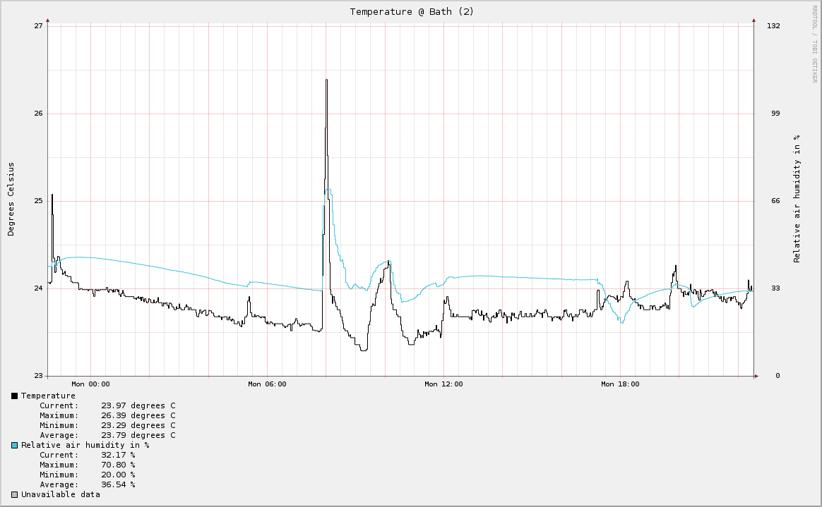
The receiver unit is connected to my home server where a small perl script converts the raw values into degrees Celcius and relative humidity and stores those values into a database using rrdtool. The first image shows the humidity in the bath room (watch the humidity raise as someone is using the shower):
What’s next
The next step is to design a neat PCB and select a small enclosure and fabricate 10 of those sensors, which I can place around the house and outside. But this will have to wait for the next blog post.